Here’s Bjorklund. He’s been dropped, stood-on and attacked by cats, yet survives. I was pissed drunk when I made this but hopefully it will provide a first inkling of the little fella’s potential:
Blurb:
Euclid’s algorithm (circa 300 BC) describes a method for computing the greatest common divisor (GCD) of two integers. It is one of the oldest numerical algorithms still in common use.
In 2003 Eric Bjorklund extended the Euclidean algorithm to address timing issues in Neutron Accelerators. He wanted to solve the following problem:
‘distribute n pulses over m “timing slots” in the most even way possible, even though n may not necessarily be an even divisor of m.’
In 2004, Godfried Toussaint demonstrated that the resulting binary patterns mirrored many familiar ostinatos (repeating rhythmic phrases) heard in diverse range of musical styles.
African rhythms are well represented and, naturally, have since appeared in South American music, modern jazz, pop, rock and dance.
– Tracklength of 1- 64 steps
– 1-64 Pulses, feeding into the algorithm.
– Full control over current playback position (rotation).
– Clock dividers (Whole note to 1/32 ).
– Solo/Mute.
– Velocity.
– Random Velocity offset – Humanisation (+/-)
– Accented notes every 1-16 steps (max velocity)
– Assignable MIDI Note.
– Assignable MIDI Channel.
– Randomization per track or all tracks.
Fine control over Master BPM (+/- 3, 1, 0.1).
Next version will bump-up to Teensy 3.1 and will feature…
USB MIDI
Performance Controls
Groove – Tick Quantization and Tick shift
Extensive preset management and fast switching
Track groupings
Touchstrip
Proximity sensors/D-beam
Tap Tempo
Apologies for the shitty video quality. But does it matter?
I’ve got the beer on ice, so tonight I will make a video demonstration of the finished item, and it has far surpassed my expectations! 🙂
Some quick snippets…
But first, here’s a catch-up on construction and materials used. Rather than explain in minute detail each step, I will for now just point to the resources that provided the most direct and useful information. They are the nuggets gleaned from numerous trawls through crappy/broken code and bad schematics.
I keep the power supply on a separate board. It’s a common diode-protected, RC filtered 5v regulated design…
The LED matrices are just too big for the breadboard, so I propped-them up on stackable headers to allow me access to the pins. I’m using 2 x MAX7219 driver chips. Connecting these to the ATMega and to each other was a breeze, however wiring the matrices themselves was a little tricky. I mostly followed the instructions here, however this wiring was not correct for my particular LED matrix (common cathode – from Tayda). I found the wiring diagram here to work for me.
The encoders were connected and via the MCP23017 I/O port expander. I got these encoders from Reichelt – they are quite stiff and they have been problematic.
Firstly they wouldn’t stay on the breadboard (legs too short!) so I made a breakout. Those funny protrustions are my attempt at hardware ‘debouncing’. I soldered sockets to the pins so that I could experiment with different capacitor values. In the end, 100n capacitors connected between each pin and common ground were best, although the encoders were still somewhat jumpy. I used a healthy dose of contact cleaner on each and this helped significantly. These encoders need to be ‘broken-in’.
In the code I am polling these controls according to this helpful post. This works well but is quite the resource drain. To circumvent this I tried using interrupts, however they proved even more problematic because they were detecting even the slightest tap of the encoders. Also, setting-up interrupts via the MCP23017 is no trivial task. I managed to fry two chips for my troubles. Interrupts are for another day….
In the next version I will abandon the mechanical encoders in favour of optical. I think the additional cost will be more than compensated by time spent, in frustration, fixing a problem that is beyond my control.
Finally there is a RGB LED which provides instant access to 7 colours as menu indicators. I’ve coded a state machine that allows me to turn 4 encoders into 40 controls, depending on what sequence of buttons is pressed. The mode is indicated by the single-or-mixed colours of the RGB. Thus there is always a clear visual indication of which menu is currently in use.
Overall, a fairly small parts count, easily obtained. Here is the Bill of Materials and sources:
#!c++

std::string bjorklund(int beats, int steps)
{
    //We can only have as many beats as we have steps (0 <= beats <= steps)
    if (beats > steps)
        beats = steps;

    //Each iteration is a process of pairing strings X and Y and the remainder from the pairings
    //X will hold the "dominant" pair (the pair that there are more of)
    std::string x = "1";
    int x_amount = beats;

    std::string y = "0";
    int y_amount = steps - beats;

    do
    {
        //Placeholder variables
        int x_temp = x_amount;
        int y_temp = y_amount;
        std::string y_copy = y;

        //Check which is the dominant pair
        if (x_temp >= y_temp)
        {
            //Set the new number of pairs for X and Y
            x_amount = y_temp;
            y_amount = x_temp - y_temp;

            //The previous dominant pair becomes the new non dominant pair
            y = x;
        }
        else
        {
            x_amount = x_temp;
            y_amount = y_temp - x_temp;
        }

        //Create the new dominant pair by combining the previous pairs
        x = x + y_copy;
    } while (x_amount > 1 && y_amount > 1);//iterate as long as the non dominant pair can be paired (if there is 1 Y left, all we can do is pair it with however many Xs are left, so we're done)

    //By this point, we have strings X and Y formed through a series of pairings of the initial strings "1" and "0"
    //X is the final dominant pair and Y is the second to last dominant pair
    std::string rhythm;
    for (int i = 1; i <= x_amount; i++)
        rhythm += x;
    for (int i = 1; i <= y_amount; i++)
        rhythm += y;
    return rhythm;
}
This was the most challenging piece of code to date. Outwardly simple, and with many existing examples in other languages, not to mention the C code example in Bjorklund’s paper, it should have been a doddle to implement on the Arduino, right?
But no. I realised the big downside to using the AVRISP: no access to the serial interface, which makes debugging impossible. Thankfully I could use the Teensy 3.1 to test my Code. But this in itself brought heartache, as there were some library conflicts with Teensyarduino. A troubling story to be sure, but In brief, I battled through ’til dawn and eventually cracked the bastard.
My overriding concern was – how much of the ATmega’s CPU time would be taken-up by using recursive function? I would have expected this to be a resource hog, and I worried that it wouldn’t handle 8 tracks simultaneously, slowing everything down. I’m happy with the current state of the MIDI clock (99.98% accurate), and this was something I didn’t want to compromise. I also witnessed some talk on the forums about Arduino’s limited stack size.
In the end, performance wildly exceeded my expectations. See the example outputs below.
Note that I have reversed the order or the patterns in alignment with the examples in Toussaint’s paper. See chapter 4 for many more examples. An interesting read for sure.
In the end, the pattern directions don’t matter, because I’ve implemented track rotation and track reverse in the main application. So…
For 8 steps and 3 pulses, the pattern is: 10010010
Bjorklund took 8.00 microseconds.
Cuban tresillo / Habanera rhythm. “It can often be heard in early rock-and-roll hits in the left-hand patterns of the piano, or played on the string bass or saxophone. A good example is the bass rhythm in Elvis Presley’s Hound Dog.“
The tresillo pattern is also found widely in West African traditional music. For example, it is played on the atoke bell in the Sohu, an Ewe dance from Ghana. The tresillo can also be recognized as the first bar of the ubiquitous two-bar clave Son given by [x . . x . . x . . . x . x . . .].
For 8 steps and 5 pulses, the pattern is: 01101101
Bjorklund took 10.00 microseconds.
Cuban cinquillo. Used extensively in jazz, 50’s rockabilly and West African traditional music. e.g hand-clapping pattern ‘Hound Dog’.
For 12 steps and 4 pulses, the pattern is: 100100100100
Bjorklund took 10.00 microseconds.
The 12/8-time Fandango clapping pattern. (I know, I know)
For 3 steps and 2 pulses, the pattern is: 011
Bjorklund took 5.00 microseconds.
E(2,3) = [x . x] is a common Afro-Cuban drum pattern. For example, it is the conga rhythm of the (6/8)-time Swing Tumbao. It is also common in Latin American music, as for example in the Cueca.
Lastly, a silly example to check performance again:
For 83 steps and 56 pulses, the pattern is: 01110110110110110110110110110110110110110111011011011011011011011011011011011011011
I’m usually the one to grumble when I come across all those meaningless, grubby 20-second videos on Youtube. But today I’m adding my own. What the hell.
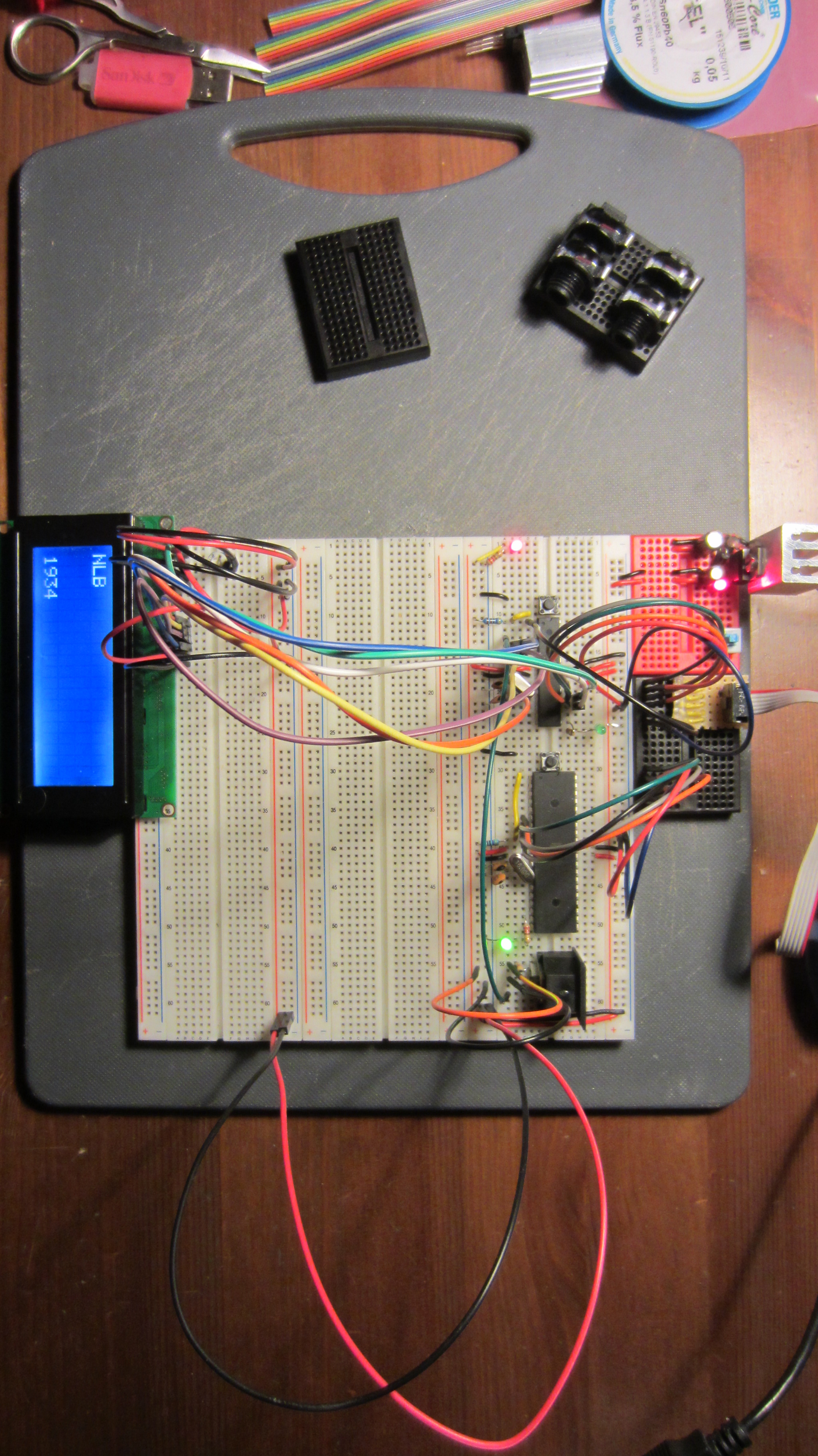
Here is Bjorklund just come to life:
At this moment I have a tight MIDI clock running on the ATMega328 at 24ppqn, with the option to go to a higher resolution if and when I trade-up to a better processor(Teensy 3.1 here I come!).
The 4 encoders and buttons are multiplexed using a single MCP2317, and the LED matrices are driven by 2 MAX7219s (both apparently counterfeit but working perfectly).
What you see are the available tempo divisions from slowest (each quarter note) to fastest (each MIDI tick) flashing across the screen.
I’ve come-up with an elegant way to deal with the note queues, rotation and sending MIDI. I can send notes on 8 tracks, remaining stable to master BPM of >300. All Looking good so far!
All that’s left to do is implement Bjorklund’s algorithm and feed it’s output to the note queue.
Then finally the controls/menu system and that’s it! It’s all optimization from there. It seems the most challenging part is documenting the process, but I’m gathering my notes…
I should be wiring-up the 4x4pole, but here I am fiddling with breadboards. Suddenly got it into my head that I must build an Euclidean Rhythm based MIDI/CV sequencer. Bjorklund’s algorithm will be used:
The problem reduces to the following: construct a binary sequence of n bits with k one’ s, such that the k one’ s are distributed as evenly as possible among the zero’ s. If k divides evenly (without remainder) into n, then the solution is obvious. For example, if n = 16 and k = 4, the solution is [1 0 0 0 1 0 0 0 1 0 0 0 1 0 0 0]. The problem of primary interest is when k and n are relatively prime numbers [23], i.e., when k and n are evenly divisible only by 1.
Toussaint discovered (only in 2004!) that the resulting patterns of spaced pulses often represent the rhythms of many word music styles. This presents a simple way to generate new and interesting drum patterns.
There are already other Euclidean generators out there, and even one in the MIDIbix Seq4, but I have my own nascent ideas, even if I only a little knowledge on how to implement them. Another distraction! 🙂
The logical conclusion to this effort should be a PCB for a unit that can act as a standalone MIDI/CV sequencer in a box, and one that is small enough to be integrated into a Eurorack setup. After some research I decided to start with Arduino. It comes with MDI libraries as standard, and already there are lots of interesting projects out there to reference.
In keeping with the DIY philosophy, I forewent the purchase of an Arduino board and instead opted to set-up a development environment using ATmega microcontroller and the Arduino libraries: – essentially to create an Arduino clone on a breadboard.
I am using the ‘standard’ Arduino chip – the ATmega328p (used in the MIDpal). As I had a spare ATmega644 (used in the Shruthi-1), I decided to breadboard it as well. The 644 is not officially supported by Arduino, however there is an Arduino-compatible bootloader called Sanguino.
There is plenty of information out there on how to breadboard these chips. The most useful video I found was this one from Notes and Volts, which helped me setup the 328p in no time.
In the process, the concept and function of the pins became clear, and I could easily map the ATmega pins to their Arduino equivalents using the following diagram:
For the 644 I used this reference and this pinout diagram:
Once hooked-up, I needed a way to program the chips. Fortuitously I had an Atmel AVRISPmkii to hand. I bought this to program my Shruthi chips and used it for all of 5 minutes a few years ago.
There are some issues to watch out for when using the AVRIPSMKii with Arduino:
The various sources I referenced all used a 10K pull-up resistor on the reset pin, however for the AVRISPMkii to work properly, this pull-up resistor must not have a value higher that 4.7KOhm. See P26 of this document.
In Win7, the Atmel USB driver conflicts with the Arduino IDE. A different driver must be installed. Full details here.
On Linux, the toolchain and associated libraries need to be installed. Further, to get the Arduino IDE working, the correct USB device permissions must be set specifically for the AVRISPMKii. This is achieved by updatinbg the UDEV rules. See P12 of this document. Note: I had to use ATTR{idProduct} instead of SYSFS{idProduct}.
If using avrdude we must always specify that we are using the the port (-P usb). See the tutorial here.
A green status LED on AVR indicates that connections are good. With the AVRISP, the board MUST be separately powered (5v) in order for the AVR to detect and program the chip.
OK, so after overcoming the AVRISP driver issues, the next task was to set the fuses and install the Arduino boatloader onto the virgin chips. This requires hooking-up the AVRISP to the correct Arduino/Sanguino Pins. Referencing the pinout diagrams above, making the connections is an easy task, but one that must be approached slowly.
Referencing the AVRISPmkii pinouts:
Just to be clear, this is pin 1:
I made a little breadboard adaptor for it…
Ending-up with something like this:
After triple-checking the connections, I fired-up Arduino IDE. After many failed attempts, I was still not able to bootload the damn things. Attempts at querying with avrdude always returned the following error:
avrdude: Device signature = 0x000000 avrdude: Yikes! Invalid device signature. Double check connections and try again, or use -F to override this check.
A web trawl suggested that this was due to the crystal not oscillating. Switching-out the crystal and trying instead a 16Mhz resonator returned the same error.
As it turned out, the default avrdude transfer speed is too fast for the virgin chips, therefore it’s necessary to adjust the baudrate (-B option in avrdude) to allow the initial communication. I didn’t realise this until after I solved it, and this was the problem that soaked-up most of my troubleshooting time. Bah!
The desperate answer in my case was to install Atmel AVR studio 6.2 – an overly torturous and bloated product (1.5Gb install), but one that bore immediate results when following this blog post.
Later, I realised that I could have done this much more quickly with Linux, and without the need for that massive Atmel install. Here are the required commands (Ubuntu).
Now fire-up Arduino IDE. No serial port is recognized on the AVRISPMKii, therefore trying to upload a sketch will return a ‘no Com port‘ error. It took me a few minutes to figure-out that you must instead ‘Upload using Programmer’ i.e press shift when sending the sketch (or just cntrl-Shift-U). Also, it’s important to ensure you are uploading to the correct board type in the Arduino IDE (Arduino UNO vs Sanguin 644).
I attached a MIDI out port and an LCD, loaded-up a simple MIDI sketch to test it.
It worked first time. A great start!
Next steps will be to wire-up some pots and buttons, and start writing the code.
To satisfy a couple of requests, I made this little vid to demonstrate non-destructive removal of the spring from standard gamepad joysticks (Xbox 360, PS3, Logitech, etc.).
If you don’t have a nephew’s games closet to raid, you can always buy the joysticks. This is my source. Tell Uwe I sent you.
Here’s where I show how to wire-them to the CV inputs of a Shruthi-1.
Firstly, the boards have been populated with resistors and most capacitors. The digital control boards are complete save for the OLEDs, buttons and pots, which will be panel-mounted. Tragically, and despite my heroic efforts at military planning/sourcing, I didn’t order enough 100n capacitors for the filter boards. I now diligently plan my next components order.
Quite some time has already been spent working on the case design and front panel. Using Inkscape, I’ve already ordered and received some test cuttings in 3mm acrylic glass. I’ve firmed-up on some nice ideas that I will expand upon in another post. Still deciding whether to invest in wooden cheeks, but then again, they can come later.
I’ve flip-flopped daily over whether to implement the Shruthi XT programmer, or stick with generic midi control. I’ve now firmly decided to not use the Programmer this time – though I did grab 2 PCBs in the latest bulk order, and I’ve already gathered the parts. The reasons are:
Using the programmer would mean direct control over only one Shruthi, which would be fine in Poly mode, but not ideal for other configurations (e.g. 4 independently-controllable monosynths).
By using the programmer I would lose CV control, and thus the ability to indulge my current joystick fetish.
I’ve got other cool ideas for the programmer. Foremost of which will be a keyboard version of the new Ladder filter. 😎
So, MIDI it is, and by chance I have an old beat-up Evolution UC-16 which I will be cannibalizing.
Quite easy to take apart….
I thought there might be an extra MIDI port hiding in there, but alas…
Now, these pots are a bit worn so they need replacing. I suspected they were 10k linear pots. A quick test confirmed this. Problem is that these pots are so welded to the PCB that the cleanest route is to just cut them off…
So now I can add my own pots and arrange then as I wish on the front panel. By also adding the keypad I will have access to 25 banks of 16 MIDI CCs, each knob being freely assignable to any CC on any channel. That’s a lot of control!
Further, this can take MIDI input directly over USB, so I can sequence the whole caboodle from a DAW if I wish. But where’s the fun in that?
And why stop there? I’m also integrating my as-yet unbuilt MIDIpal to make this a super-charged master keyboard. Better than the plastic shit available these days, and fully customised. Cheaper too.
MIDIpal has 8 CV inputs = Joystick pron! hehe
The bonus is that, with 4 Shruthis I will also have a routable 4-in 4-out MIDI interface.
I’ve had some time to return to and investigate the wheel connectors on the MKE.
Remember that, when I tested the Novation wheels the range was minuscule. It turns out that the wheel receivers are calibrated to Doepfer’s own standard. It also accounts for the narrow range wheels have normally, due to the spring on the pitch wheel and the large diameters.
A closer look at the Novation wheels revealed 2 x 5K linear pots like so:
The Doepfers are 10K so I decided to use a trusty joystick, this time with the spring intact, to see if it could be used as a mini pitch-wheel.
The result was disappointing. At rest pitch was always at maximum, and moving the stick to one side again swept through the range an a narrow band. No, this won’t do.
To see if I could exactly define this range, I attached a standard 10k linear pot. Again, same result. Hmmm.
So, how could I limit the range of a pot?
Thankfully the answer came quickly and it’s such a simple fix it’s almost embarrassing…
…how about if I just twist the Novation pots in their housing? This way I could tune the range by hand. So, after cleaning the solder off the pins, I plugged the Novation wheels back-in, loosened the pots and re-orientated them.
First, the potentiometer tabs needed to be clipped-off. (I now know what they’re for – holding the pot in place!)
Then plugged-in (after removing the solder I left on the pins 😛
And, by Jove, it works like a charm!
The main caveat is when re-orienting the pitch-wheel pot – you need to account for the spring, so best to have MIDIox or other such monitor open to see when you’re at zero before tightening the nut. The pots are d-shaft, so in this case I could easily find zero.
Here they are with their pots newly-oriented and wheels re-fitted.
Everything is now up-and-running with the MKE. Superb!
Buoyed by this success, I’ve decided to adopt a modular approach to the 4×4 pole enclusure, wherein the synth section will be detachable from the Keyboard.
Because, who knows, I might want to build a 4xLadder Filter at some stage…
I’ve been a bad boy, skiving-off to further molest my Shruthi-1.
These mods have been brewing for a while, as I fiddled and took notes from the Mutable Instruments forum and the Mutable Wiki. They are surprisingly easy to implement, once you gather the right components, and they are providing good learning points for the 4×4 build.
KK, on with the details…
There are 3 filter switches…
1. Select 2 or 4 pole filter.
2. Choose either of 2 bandpass modes. I haven’t quite got this one working yet. I think I need a new switch.
3. A switch to allow the audio input to be used as FM modulator on the filter. An input level knob is also added to provide more control. Initial tests of this are very promising!
And two new knobs…
1. A separate FM control knob allows a degree of filter feedback. It’s quite subtle, but adds lovely harmonics to the low-end. I’m going to see if I can beef this up.
EDIT: Thanks to the helpful guys on Mutable forum, I removed the 47k resistor and used a C10K reverse audio pot to give a nice transition from subtle to a harsher FM grit. Lovely.
2. Then there is the drive knob. This one is great! It overdrives to distortion very nicely. An output volume control is necessary to attenuate, because this can get loud. Shruthi size belies and delights yet again.
I’ve also put a LED on CV1 out. This can be hooked-up in the mod-matrix to provide visual feedback of modulation parameters, including tempo-synced LFOs. It works brilliantly, and the brightness is also adjustable from the mod matrix. CV2 is also available and will be used for the same purpose. This is going to look great on the 4x4Pole!
And of course, the 2 joysticks. I am loving these. In a moment of madness I imagined an interface dominated by an army of these fellas. It surely will happen 😛
Now, I could squeeze all these entrails into the standard enclosure, but I feel that would be unfair to poor Shruthi. I’ve really gutted this guy, so it’s time to buy some new clothes, with enough space to include these and any future mods. I already partially atoned by replacing the filter caps with fancy styroflex thingies. That’s a new OLED too which makes a big difference. Finally, I took the chance to re-align the boards, and now everything is where it should be.
I’ve already designed and ordered the case: the Shruthi NoisyLitteBugger edition should be ready next week 😉
Amongst several boxes of goodies to arrive today was the Doepfer MKE. I took a bit of a punt on this, as I wasn’t certain that my scavenged Novation KS4 keybed would work. There’s a surprising dearth of information about the Novation keybeds. But all the clues pointed to it being a Fatar keybed (Diode matrix, Aftertouch strip, 16 Micromatch connectors), and thus fully compatible with the MKE.
I thought it would be an opportune time to pick-up a Doepfer DIY synth for the next project – the slide into Modular with Little Dieter. For now, let’s focus on the MKE….
It came with a 9v power supply. Overall it feels pretty well-built and sturdy. The LCD is adequate, but those buttons have gotta go. Yuck.
I wanted a quick test so I hooked-up the wheels, with MKE spitting data out to MIDOX.
Modwheel and Pitchwheel are recognised, however the range is extremely narrow. The MKE manual makes mention of these inputs being tailored towards Doepfer’s own ‘accessories’:
‘…the voltage range ~ 0 … 1.6 Volt corresponds to the Midi data range 0 … 127. The reason for this limited voltage range is the rotating angle of the wheels we offer as spare parts. An output voltage range of ~ 0…1.6V was measured for these wheels if they are connected to GND and +5V as they do not cover the complete rotating angle because of the end stoppers.’
This is going to need some research, so another day. But what about the keyboard?
First I needed to make cables using 16-strand flat ribbon and 2×8 pole male Micromatch connectors, and thus saving myself a small fortune.
With both keyboard cables connected, I could immediately see the notes being received by MIDIOX, but the zones were reversed. A quick swap of the cables remedied that.
Keyboard working! And with a smooth velocity response 😎
And so to Aftertouch. I was most uncertain about this one working. The Fatar cable has four pins, but the MKE only accepts three. After a while of random and fruitless jumper-switching I hit upon the brilliant idea of reading the MKE manual (doh!). There it was, in the appendix, the key to success. Only two connections are needed, necessitating a little hack using header pins and a dexterous disposition …
My scepticism came crashing down as the pressure signals appear on screen. A quick change of settings from the crappy-but-adequate interface and aftertouch working perfectly. What’s more, the aftertouch curve seems just fine, so no messing with switching resistors. Yeeeehaaaw…
😀
Right, I am feeling pretty good now. Just mod- and pitch-wheels to calibrate and I’ve got myself a very nice, expressive master keyboard.
I built my first shruthi last year and the poor little bugger has been poked and prodded since. Not only is it a great synthesizer, it is also a fun playground for a beginner audio noodler like myself.
One of the standard Shruthi mods is to attach controllers to the 4 CV inputs. These can be mapped to multiple parameters in the mod matrix, providing oodles of modulation possibilities.This could be controlled by knobs or touchpads or the like.
The most accessible method is to attach a 10k linear pot to the points on the control board (left of the LCD).
Looking at the pot, the legs should be connected thus: 1: +5V
2: CV (1-4)
3: GND
On the Mutable Instruments forums I read that PS3 gamepad joysticks are basically 2 10K linear pots assigned to X and Y coordinates. The only problem is that the spring can’t be removed without destroying the mechanism. I want the joystick to stay where I put it.
After a lot of searching, it was apparent that few joystick met this criterion, and they tended to be expensive; 45 euro for the Doepfer version, and an extra tenner for the shaft. Bugger that.
Then I came across this excellent blog post detailing how to remove the springs from an Xbox controller.
Not having an Xbox controller to hand, I instead ripped-open an old, broken Logitech PC gamepad I had thankfully kept – along with many other boxes of junk. The hoarder vindicated 😀
EDIT: You can also buy the joystick components separately if you wish. Here’s a good source: Uk-Electronics.
Click pictures for full size:
Removing the PCBs is easy…
..and there are our little beauties..
Noticing that the joysticks were similar to the Xbox ones, I proceeded to follow instructions in removing them from the PCB and then their springs.
The joystick housing need to be carefully de-soldered from the gamepad PCB…in this case there were 15 points attached to the board. Make sure they are all free before prising the whole thing free. Solder wick is essential.
The spring and button are house in the plastic base. Bend the metal legs to release it. It just pops out.
With base removed (and thus spring and button)…
Once the spring is out the mechanism is unsupported and will probably fall apart. But it’s easy to re-assemble – it’s just 2 pieces. The potentiometers can be snapped-off and reattached also. Very elegant design. To keep the shaft in place permanently, I soldered small wire supports like so:
For testing, I plonked it onto a piece of polystyrene…
Then I wired-up both sets of pins…
..and connected them to the Shruthi CV points…
At first I thought it wasn’t working, however I had wired the wrong CV pads! Switching to the correct ones in the Mod matrix brought a huge smile to my face. The joystick works perfectly, goes where you want it, and STAYS there.
WooHoo!
Initially I kept the wires long for a reason; I wanted to test how sensitive the CV inputs would be to interference. At this length I noticed no adverse effects.
Now, how to house it?
Conveniently, it turns out that all the joystick legs will fit snugly into the honeycomb side panels, but they need affixing. However the pins are close together, so some insulation is in order. I used some heat-shrink tubing. To keep things tidy should I wish to re-wire, I attached all GRN and 5V wires to pins (discarded resistor legs), leaving just single pins to be soldered to the control board.
Notice that the wiring must be consistent if you want both joysticks to behave in the same way.
There’s plenty of room for the wires to fit snugly in the case. Note that the additional switch is not needed – it for 2/4 pole filter modes (another easy mod).
For today, to keep everything steady. I’m using some ‘blu-tack’. I’m waiting for extra components for more mods, so I’ll be taking it apart again soon. When satisfied I will probably glue them on. I also found two tiny covers to put on the shafts. Cute.
And there you have it: 2 cheap (free) modulation joysticks, without springs, for your Shruthi, or any other purpose you might be dreaming. I know I am….
Timelapse of my Anushri build over 3 sessions.
Audio is recording of the first-noodle. All sounds from Anushri in a single pass, only light reverb used.
Great fun to build and play. Listen to that filter!


